

 English
 русский
 عربى
عربى Deutsch
A well-designed mold is the difference between a casting that flies through production and one that burns through budget in trial shots. In aluminum die casting, the mold locks in achievable geometry, surface quality, dimensional consistency, and cycle time before the first part is ever produced. If the mold is weak, the skill of the operator, the power of the press, and the speed of the machining center cannot compensate.
This guide explains what an aluminum die casting mold is, which components matter, which design parameters deserve the most review, and how to evaluate a mold supplier so the weak points are found before the tooling is released, not after.
What Is an Aluminum Die Casting Mold?
An aluminum die casting mold, usually called a die, is a reusable steel tool that gives molten aluminum its final shape under high pressure and high speed. The mold has two hardened tool steel halves. The cover die stays on the stationary platen and contains the cavity on the injection side, while the ejector die moves with the opening stroke and carries the pins that release the finished part.
In production, the two halves are clamped together with enough force to resist the injection pressure. Molten aluminum at roughly 600 to 700 degrees Celsius is pushed into the cavity at pressures that commonly reach 300 to 1,500 bar, and the shot solidifies within seconds because the steel die conducts heat away quickly. Every cycle repeats the same thermal and mechanical shock, which is why mold steel grade, heat treatment, and cooling channel design matter as much as the cavity shape itself.
Main Components of an Aluminum Die Casting Mold
The individual parts of the mold have a direct effect on fill behavior, solidification, dimensional accuracy, trimming work, and tool life. This list shows the components that should always be reviewed in a tooling assessment.
| Component | Function | Main influence |
|---|---|---|
| Cover die (fixed half) | Holds the cavity on the injection side | Defines the fixed side of the part and the gate area |
| Ejector die (moving half) | Carries ejector pins and moving cores | Controls ejection and undercut release |
| Runner system | Guides molten aluminum to the cavity gate | Affects fill speed, temperature loss, and flow direction |
| Overflow and venting | Collects the cold metal front and exhausts air | Determines porosity level and edge filling |
| Ejector pins | Push the solidified casting out of the die | Determines surface marks and release force |
| Cooling channels | Circulate water or oil inside the mold | Set solidification time, shrinkage, and cycle time |
| Moving cores | Form side features and undercuts | Adds mechanism complexity but improves part shape |
A mold drawing is not just a cavity shape. It is a thermal and flow plan. If the overflow volume is too small, porosity collects close to the gate. If a cooling channel is placed unevenly around a thick boss, the casting can distort when the ejector pins push it out. Reviewing the mold at this level of detail prevents surprises later in serial production.
Mold Design Factors That Control Part Quality
Most casting defects can be traced back to decisions made before the steel is cut. These are the factors to review first.
Draft Angles
Walls that are parallel to the mold opening direction need a taper called draft. Without enough draft, ejection force rises, surfaces tear, and ejector pins leave deep marks. For aluminum die casting, 0.5 to 2 degrees on outer walls and 1 to 3 degrees on inner or deep walls is a realistic starting point. Deep pockets and internal ribs need more taper.
Wall Thickness
Aluminum die casting works best with uniform walls. Typical structural housings are designed at 2 to 4 mm, and thicker segments should be cored out or stiffened with ribs. When thin and thick sections meet without a transition, shrinkage in the thicker section creates porosity or sink marks that appear only after machining.
Fillets and Ribs
Sharp internal corners block metal flow and become stress concentrators in service. The mold designer should add fillet radii at internal corners and use ribs to stiffen flat areas. This approach keeps the part light while maintaining stiffness, which matters for automotive housing applications.
Gating and Cooling Layout
The gate position determines how the cavity fills, where weld lines form, and what kind of trimming is needed after the shot. The cooling channel layout determines the direction of solidification. When filling and cooling are balanced, distortion, porosity, and cycle time remain under control.
Typical Design Ranges for an Aluminum Die Casting Mold
| Design parameter | Typical range |
|---|---|
| Draft angle, outer walls | 0.5 to 2 degrees |
| Draft angle, inner walls and ribs | 1 to 3 degrees |
| Nominal wall thickness | 2 to 4 mm |
| Machining allowance for finished surfaces | 0.5 to 1.5 mm |
| Minimum fillet radius | 0.5 to 1 mm |
Common Types of Molds in Aluminum Die Casting
Which mold style you choose depends on the product phase and the production volume.
- Prototype dies: Simplified tooling that produces a small number of samples for design validation. They are quick to modify and much cheaper than production tooling.
- Production dies: Hardened tool steel molds engineered for tens of thousands of shots. The initial cost is higher, but cost per part drops.
- Single-cavity and multi-cavity dies: One cavity makes one part per cycle; multiple cavities increase output but require a balanced runner to avoid inconsistent filling.
- Unit dies: Interchangeable cavity inserts mounted in a common mold base, a good fit for medium volumes and frequent part changes.
- Trim dies: Secondary dies used with a press to trim the runner, overflows, and flash from the cast part.
Trim dies are often underestimated in the tooling budget. Flash removal is non-value-added work, and a badly aligned trim die can damage a casting that has already passed the main process.
 Precision Trimming Mold Die Casting for Reliable Flash RemovalThis supplier combines mold design, die casting, and post-processing on one site, with large tonnage machines and CMM/CT inspection to support trim tooling accuracy and protect finished castings.View Product →
What to Check When Choosing an Aluminum Die Casting Mold Supplier
Most projects fail not because the cavity shape is wrong, but because the supplier cannot prove the mold is right. Check these points before signing the tooling contract.
Steel Grade and Heat Treatment
Premium molds for aluminum die casting are normally made from H13 tool steel, hardened, and surface treated to resist heat checking and washout. Ask for the material certificate and the heat treatment record. If the steel or the treatment is vague, the mold life and casting consistency will be uncertain.
Simulation Before Cutting
A supplier that runs die filling and solidification simulation can spot air traps, cold shuts, and shrink defects before steel is cut. Trial shots then confirm the simulation, instead of relying on trial-and-error at the press.
Dimensional and Internal Quality Verification
Cavity dimensions, parting line contact, ejector pin positions, and cooling channel locations should be verified on a coordinate measuring machine. For sealing-critical castings, porosity inside the part should be checked with X-ray or industrial CT. A mold delivered without these records carries hidden risk.
Process Ownership
The mold is only half of the production equation. Machine settings, part handling after ejection, and the machining stock removal all affect the final dimension. Partnering with an integrated aluminum die casting manufacturer that designs the mold in the same plant shortens iteration cycles and keeps responsibility in one place.
Why an Integrated Mold and Casting Partner Lowers Risk
When the mold is designed in the same facility that runs the press and the machining center, feedback is immediate. A porosity indication on the first shot is analyzed the same day, and the cavity can be adjusted without a negotiation loop between separate vendors. For time-sensitive programs, this directly shortens development time.
Integration matters most for parts with complex internal features, sealing requirements, or thin walls, because these features are solved at the mold stage. Precision casting directly affects the reliability of structural parts such as new energy vehicle motor housings, where dimensional accuracy and dense microstructure protect assembly fit and cooling performance.
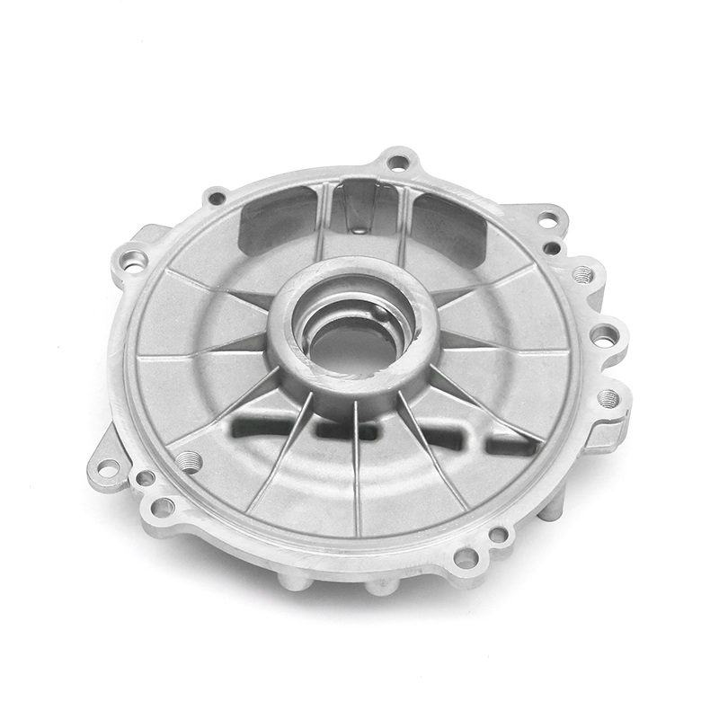 New Energy Motor Housing Die Casting with Integrated Quality ControlMotor housings require strength, lightweight design, heat dissipation, and corrosion resistance. This maker offers integrated tooling and casting with IATF 16949 and advanced inspection for structural reliability.View Product →
At Ningbo Fenda New Energy Technology, this integrated model runs on a 15,000-square-meter site with 6 aluminum die casting machines from 400 to 2,000 tonnes, 80 high-speed precision machining centers, more than 30 special-process units covering friction stir welding and electrical discharge machining, and inspection equipment that includes coordinate measuring machines, industrial CT, spectrometers, and multiple air-tightness testers. The engineering team that designs the mold also verifies the casting, the machining, and the final sealing performance under the IATF 16949 quality management system.
For housings that must hold pressure and cooling fluid, such as water-cooled electronic control units, the mold design must control thin-wall consistency and leak paths at the same time. This is exactly the geometry where integrated tooling experience pays off in serial production.
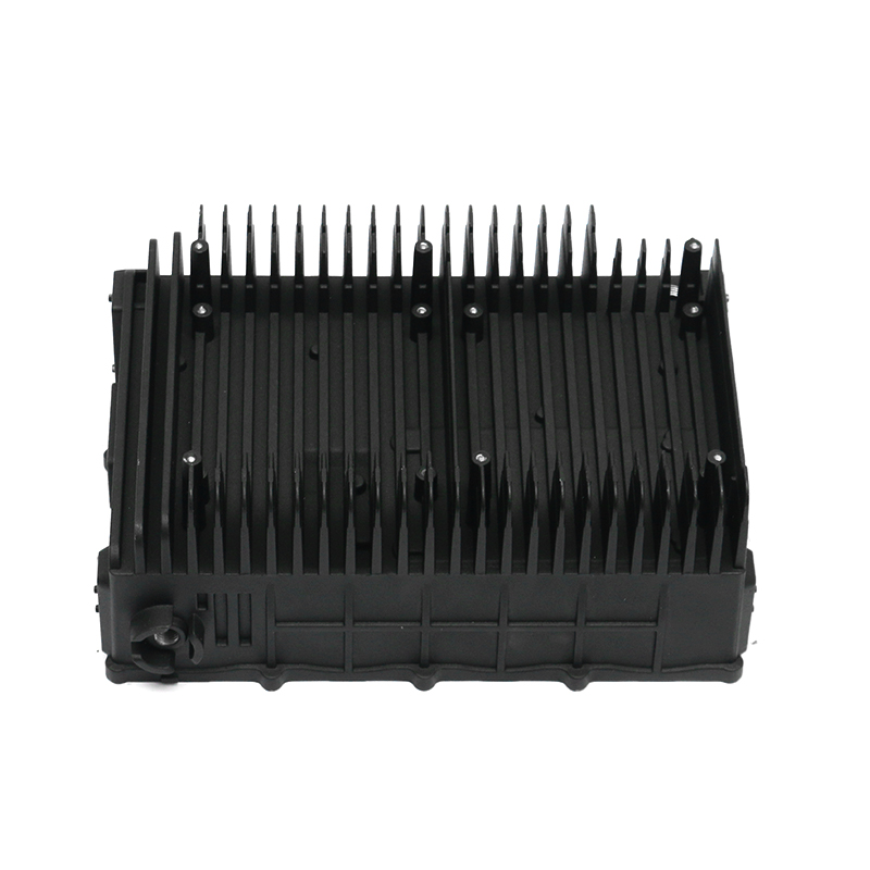
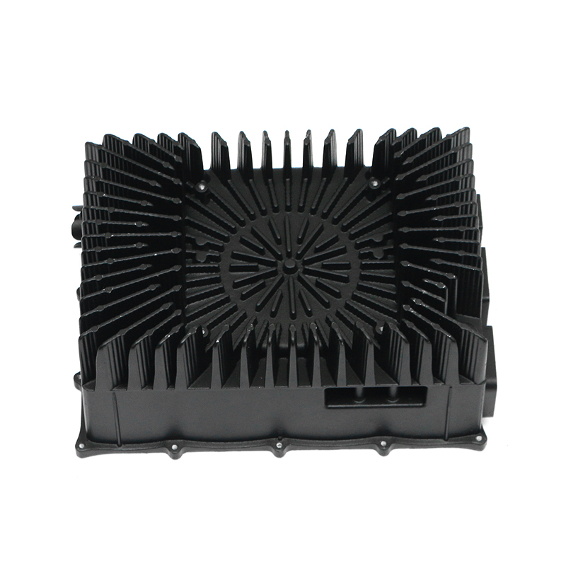
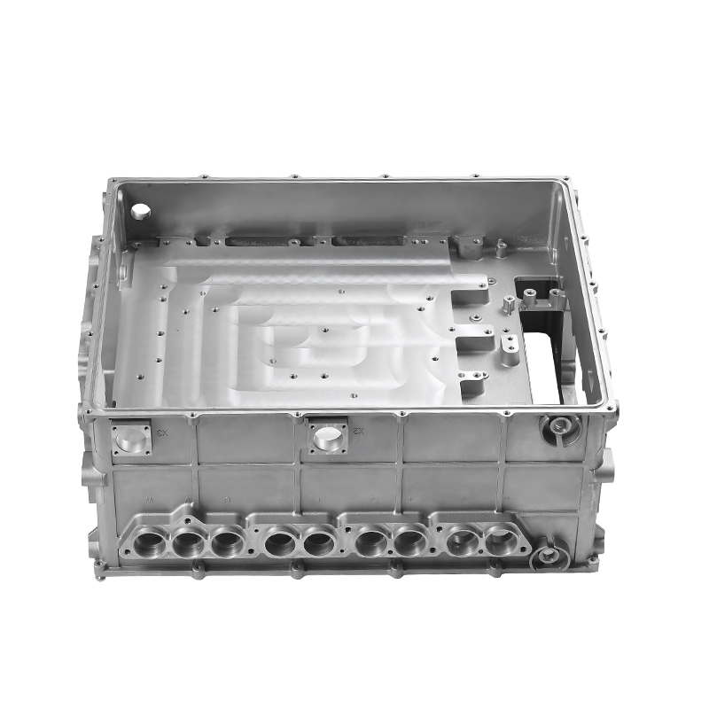 Water-Cooled Electronic Control Housing Die Casting ExpertiseFor housings that must hold fluid and maintain thin-wall consistency, this supplier's integrated mold and casting experience helps control leak paths and supports serial production of sealed electronic units.View Product →