

 English
 русский
 عربى
عربى Deutsch
The Foundational Component for High-Efficiency Electric Powertrains
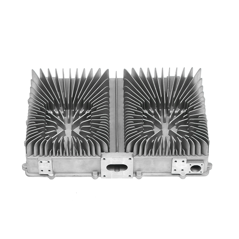
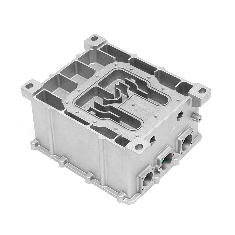
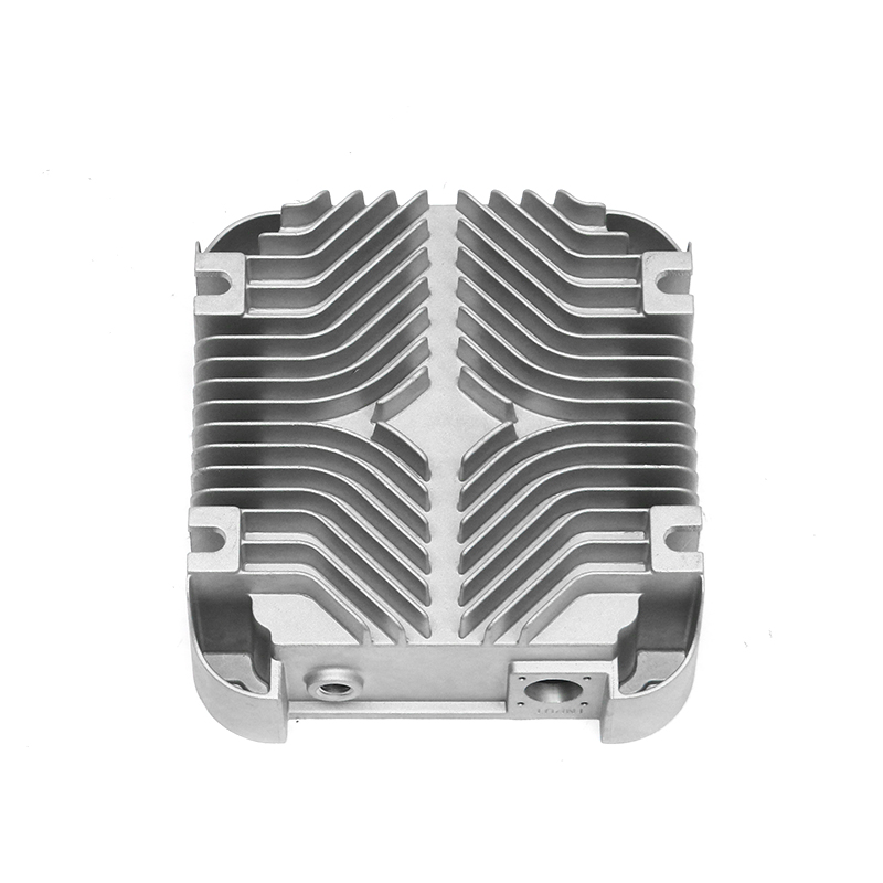
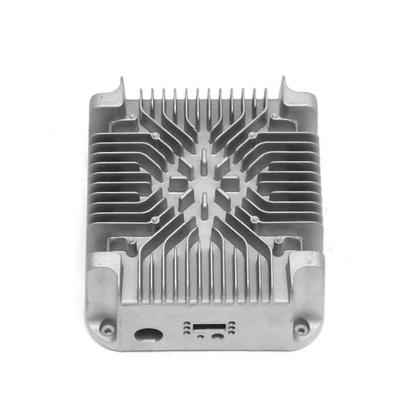
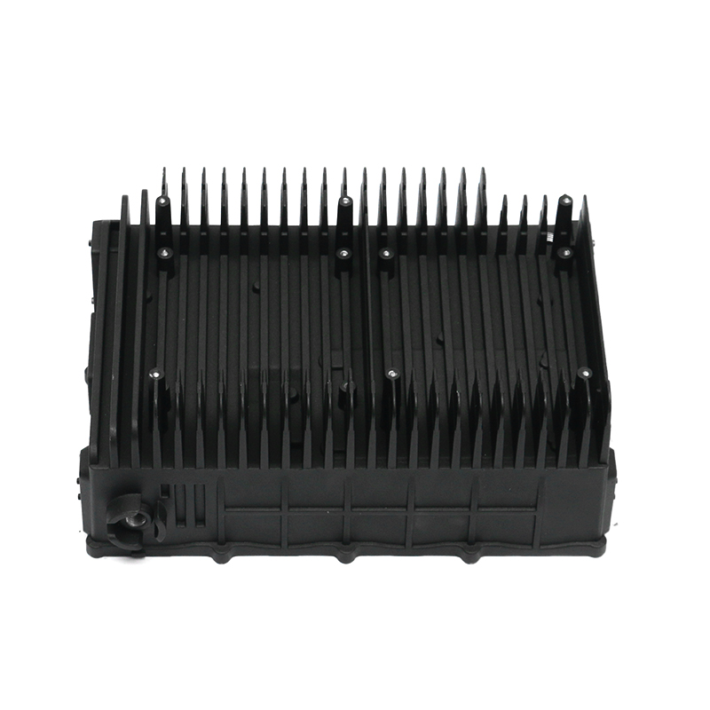
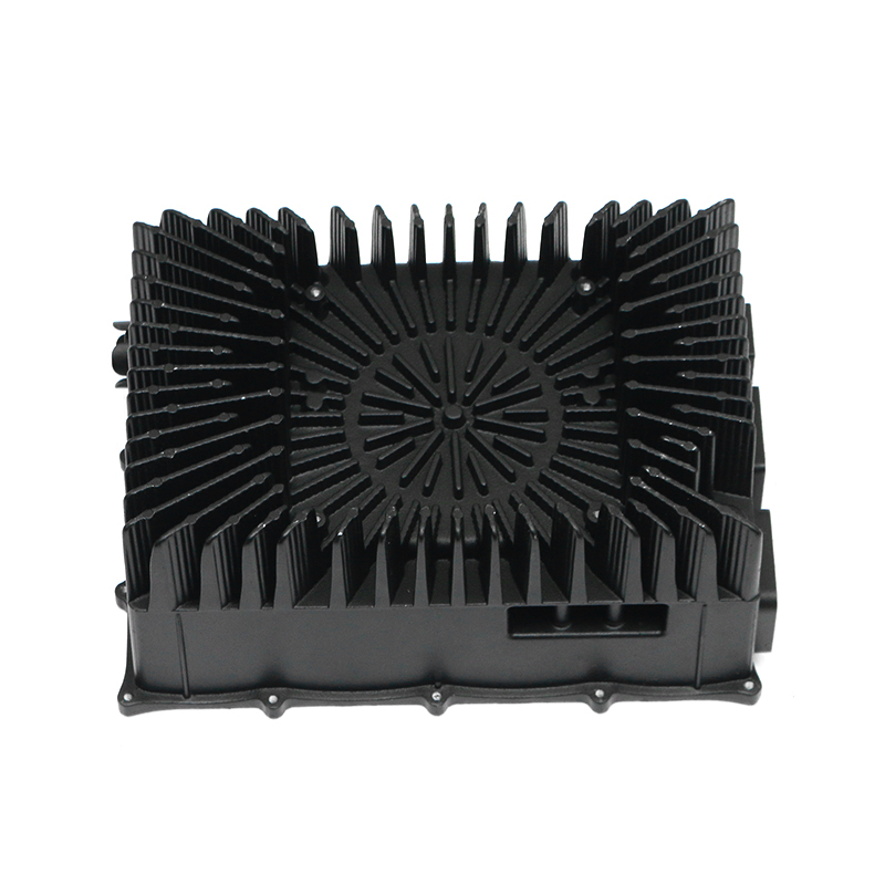
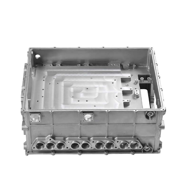
New energy motor housing die casting is the definitive manufacturing process for creating the complex, structurally sound enclosures required by modern electric vehicle (EV) traction motors. By leveraging high-pressure die casting (HPDC) with high-fluidity aluminum alloys, automotive manufacturers can consolidate the motor stator shell, integrated liquid cooling jackets, and structural mounting brackets into a single, lightweight component, reducing total housing weight by up to 30% compared to traditional multi-piece assemblies. This monolithic approach provides exceptional torsional rigidity, precise dimensional tolerances for bearing alignments, and optimal sealing against fluid leaks. As the automotive industry pushes toward 800V architectures and motor speeds exceeding 20,000 RPM, advanced die-cast housings serve as a critical asset in managing extreme mechanical forces and continuous thermal dissipation.
Industrial EV powertrains require rapid, continuous thermal regulation to prevent permanent magnet demagnetization and stator insulation failure. Unlike internal combustion engine blocks, a new energy motor housing features thin-walled, intricate geometric pathways designed to route liquid coolant directly around the stator perimeter. Manufacturing these structures requires precise structural control during metal injection to prevent internal porosity, micro-cracks, and shrinkage cavities. Achieving these rigorous requirements depends on the integration of ultra-high vacuum systems, advanced thermal modeling of the die steel, and automated real-time shot controls within the casting cell.
Metallurgical Selection and Mechanical Property Optimization
The structural demands of an electric vehicle traction motor require a delicate balance between high tensile strength, elongation capabilities, and thermal conductivity. The alloy selected must flow smoothly into complex, thin-walled die cavities without compromising the final component's structural durability.
AlSi10MgMn and Heat-Treatment-Free Alloys
Traditional aluminum alloys require multi-stage T6 heat treatments to achieve maximum strength, but this thermal exposure can introduce dimensional warping in large, thin-walled motor housings. To avoid this, modern die casting facilities use specialized AlSi10MgMn formulations or proprietary heat-treatment-free aluminum-silicon-magnesium alloys. These advanced alloys achieve a yield strength exceeding 150 MPa and an elongation rate greater than 7% in the as-cast state. The addition of manganese prevents the alloy from sticking to the die steel, while low iron content ensures the micro-structural matrix resists cracking under high operational loads.
Microstructural Density and Thermal Conductivity Management
Maintaining high structural density is vital for maximizing thermal conductivity, which typically ranges from 110 to 140 W/m·K in these alloys. During the rapid solidification phase, if dissolved hydrogen or ambient gases become trapped in the aluminum matrix, the resulting gas pores act as thermal barriers, reducing heat transfer efficiency. Precise melt-refining operations, using rotary degassing with argon gas, reduce hydrogen content to below 0.1 cm³ per 100g of aluminum, ensuring a highly uniform grain structure that accelerates heat transfer from the active motor components into the cooling medium.
The Process Mechanics of Advanced High-Pressure Die Casting
Manufacturing a complex new energy motor housing requires ultra-large die casting machines, often with clamping forces ranging from 3,500 to over 6,000 metric tons. The production sequence is tightly managed by automated real-time control systems to handle the material velocity and pressure changes required during each casting injection cycle.
Ultra-High Vacuum Extraction Systems
To achieve pore-free structural castings, the mold cavity is paired with a high-capacity vacuum system capable of pulling a vacuum below 20 mbar within milliseconds before metal injection begins. This rapid extraction removes ambient air and volatile gases generated by die lubricants. Eliminating these gases allows the molten alloy to fill complex, thin-walled profiles without encountering air resistance, eliminating gas entrapment defects and ensuring the housing passes rigorous high-pressure leak testing.
Multi-Stage Real-Time Shot Control
The injection plunger operates on a multi-stage velocity curve. In the first phase, the plunger moves slowly to accumulate the metal and avoid trapping air within the shot sleeve. As the metal reaches the gate entrance, the machine transitions instantly to the second phase, with injection speeds accelerating past 6.0 m/s to fill the entire cavity in less than 80 milliseconds. Finally, an intensification pressure of over 90 MPa is applied during solidification to compress any remaining micro-shrinkage voids, ensuring high structural density throughout the housing.
Comparative Analysis: Die-Cast Motor Housings vs. Alternative Methods
Selecting the right manufacturing process for a new energy motor housing requires balancing production throughput against structural weight, component consolidation, and thermal performance. The table below compares high-pressure vacuum die casting with alternative manufacturing methods like low-pressure permanent mold casting and multi-piece extruded assemblies.
| Engineering Parameter | Vacuum High-Pressure Die Casting | Low-Pressure Permanent Mold (LPPM) | Extruded Aluminum Shell + Welded End Caps |
|---|---|---|---|
| Production Cycle Time | 60 - 90 seconds per unit | 5 - 8 minutes per unit | Requires multi-stage welding and CNC machining |
| Minimum Achieveable Wall Thickness | 2.0 mm - 3.0 mm | 4.5 mm - 6.0 mm | 3.5 mm minimum (uniform) |
| Level of Component Integration | High (Monolithic shell, cooling jacket, brackets) | Moderate (Requires sacrificial sand cores) | Low (Requires separate parts and assembly) |
| Dimensional Precision (As-Cast) | +/- 0.15 mm | +/- 0.40 mm | Dependent on extrusion profiles |
| Total Relative Production Cost | Low (Highly economical for mass production) | Moderate | High due to multi-step labor |
Cooling Jacket Configuration and Core Insertion Technologies
The design of the integrated liquid cooling path is one of the most critical elements of a new energy motor housing. To route liquid glycol directly around the hot stator core, tool designers use two primary manufacturing methods.
Sacrifical Salt Core Technology
To create seamless, helical water jackets inside a single monolithic die casting, advanced operations utilize high-density sacrificial salt cores. These water-soluble cores are pressed from highly refined salt mixes and placed directly into the die cavity prior to metal injection. The salt core can withstand metal injection pressures up to 100 MPa without losing its shape. After the part is ejected and cooled, the housing is flushed with high-pressure water, dissolving the salt core and leaving behind a smooth, joint-free internal cooling channel that eliminates fluid leak paths.
Open-Channel Casting with Friction Stir Welding
An alternative production path involves casting the motor housing with an open, outer cooling groove array using permanent steel slides. This avoids the use of sacrificial cores, allowing for faster casting cycle times. Once the housing is cast and cleaned, a separate aluminum sleeve or cover is pressed over the open channels. Friction stir welding (FSW) is then used to seal the cover, creating a structural, leak-proof bond that can withstand continuous operational coolant loop pressures exceeding 4.5 bar without risk of delamination.
Quality Control, Testing Standards, and Reliability Metrics
Because a failure in a motor housing can expose high-voltage stator fields to liquid coolant, quality assurance processes require comprehensive, non-destructive testing (NDT) across high-volume production runs.
High-Definition Inline Computed Tomography
Finished motor housings are routed through automated, inline industrial X-ray or computed tomography (CT) scanners. This non-destructive inspection scans the casting in 3D to check for internal defects. Any micro-porosity bubble larger than 0.2 mm within critical sealing surfaces or bearing locations causes the part to be automatically rejected. This rigorous check ensures the part can reliably handle high-torque mechanical loads and maintain long-term dimensional stability.
Differential Pressure Air and Helium Leak Testing
To ensure the integrated water jacket is sealed, every single casting is mounted to an automated leak testing station. The cooling channels are sealed and pressurized with a helium gas tracer mix. The maximum allowable leakage limit is restricted to under 2 sccm (standard cubic centimeters per minute) under a test pressure of 5 bar. This level of testing confirms the integrity of the casting wall, ensuring that no coolant can migrate into the high-voltage motor windings over the operational lifespan of the vehicle.
Operational Maintenance and Tooling Protection Best Practices
Maintaining tight dimensional tolerances over long production runs requires strict tool maintenance and surface treatment protocols. The molds used for casting large new energy motor housings are subject to extreme thermal shocks and mechanical wear during operation.
- Premium Die Steel Selection: Mold cores and cavity inserts are made from premium hot-work tool steels like DIEVAR or premium H13. These materials undergo vacuum heat treatment to reach a uniform hardness of 48 to 52 HRC, providing high resistance to thermal checking.
- Multi-Layered Surface Treatment: To prevent erosive wear from high-velocity aluminum gates, the tool surfaces are treated with advanced physical vapor deposition (PVD) coatings like titanium aluminum nitride (TiAlN). This micro-coating acts as a thermal barrier, extending tool service life by up to 50%.
- Automated Micro-Lubrication Systems: Before each machine closure, an automated robotic spray manifold applies a highly consistent, minimal film of water-free electrostatic die lubricant. This micro-spray reduces thermal shock on the die face and ensures clean part ejection without distorting thin-walled sections.
- Regular Stress-Relief Tempering: After fixed production cycles—typically every 15,000 casting shots—the die elements are removed and placed in a stress-relief tempering furnace. This process removes accumulated internal stresses and prevents macro-cracking across the main tool body, preserving dimensional accuracy.