

 English
 русский
 عربى
عربى Deutsch
The Technical Solution for Next-Generation Electronic Thermal Management
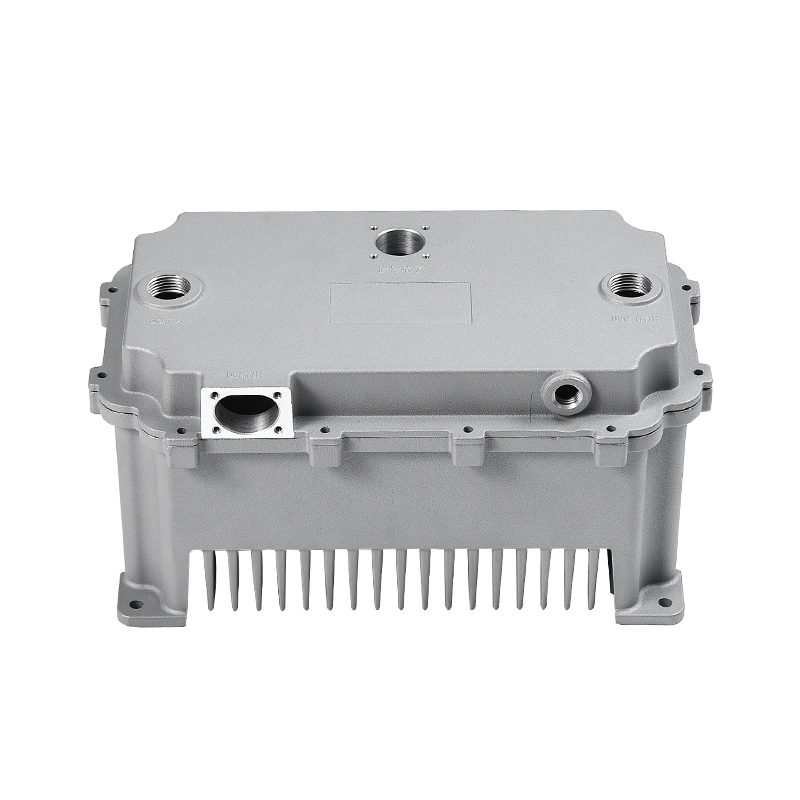
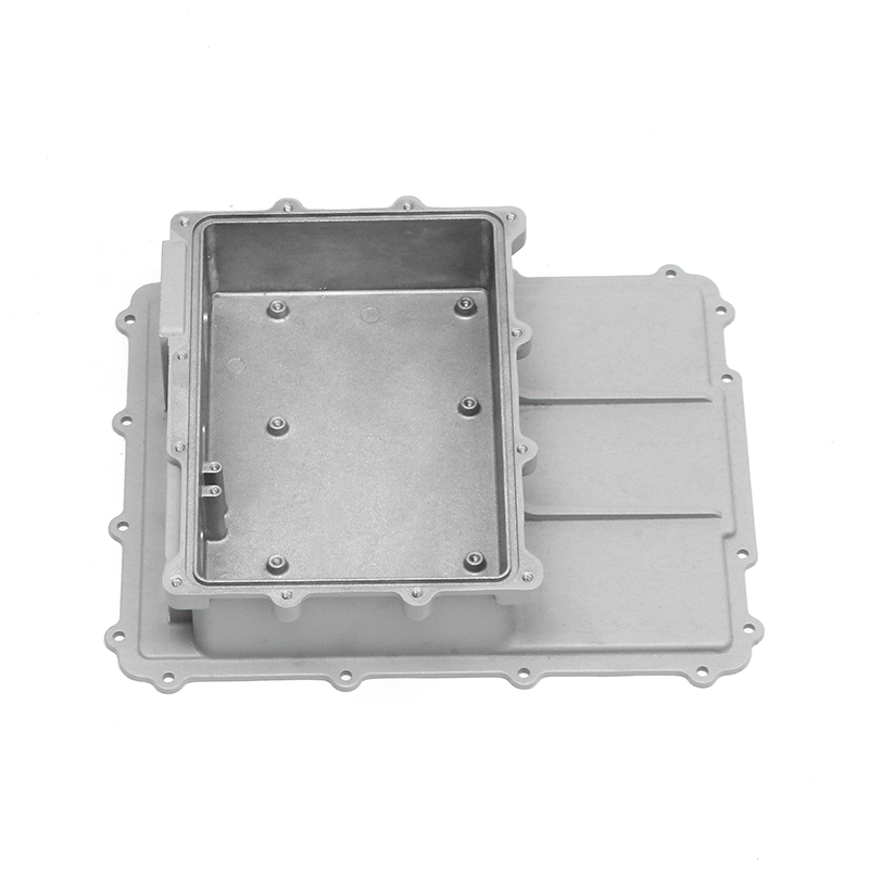
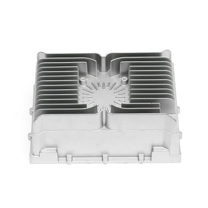
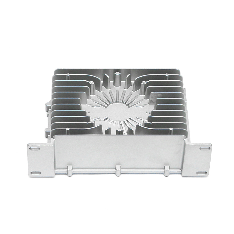
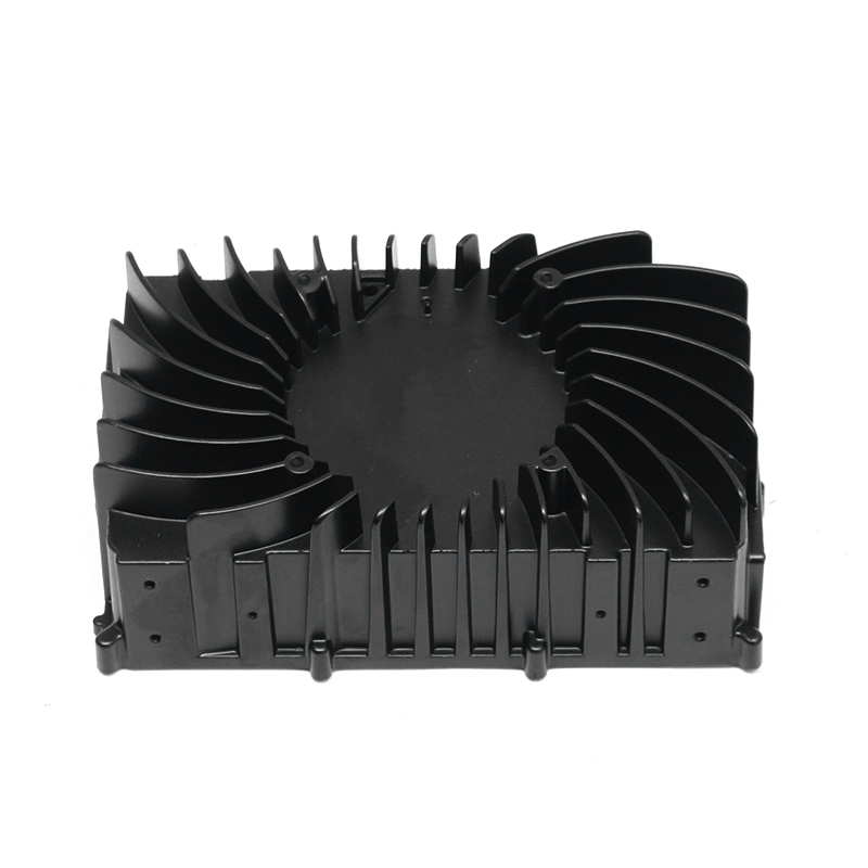
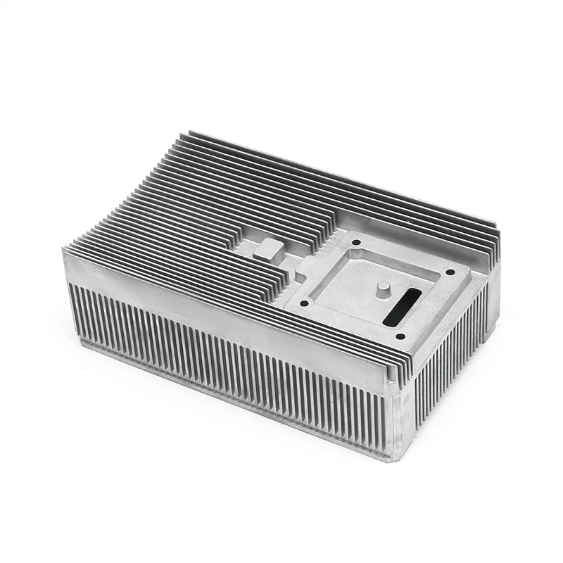
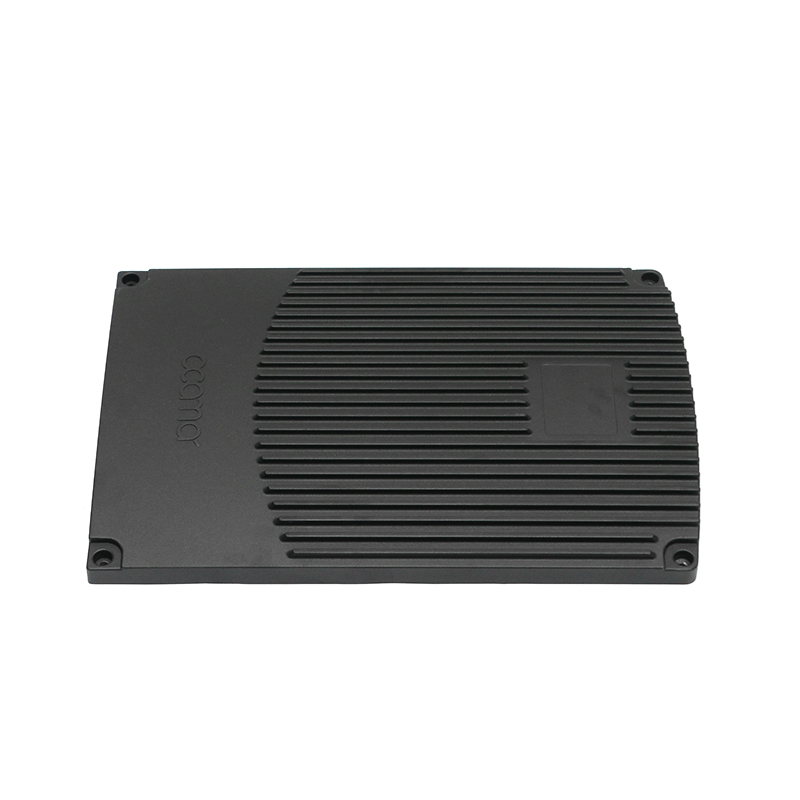
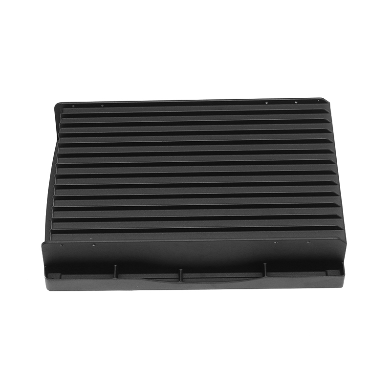
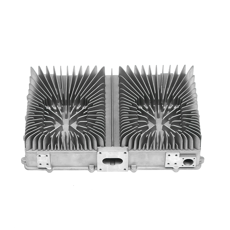
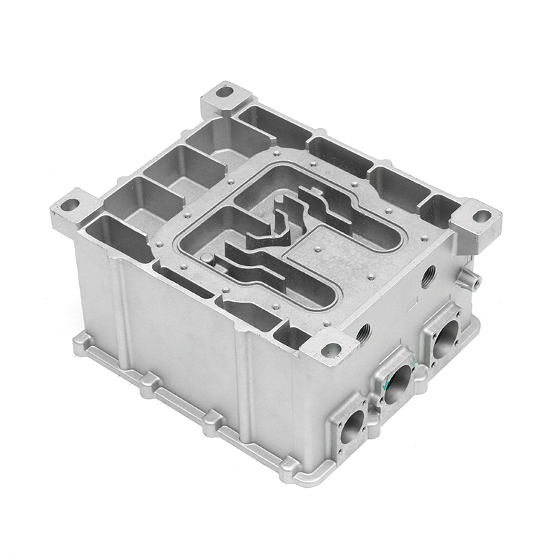
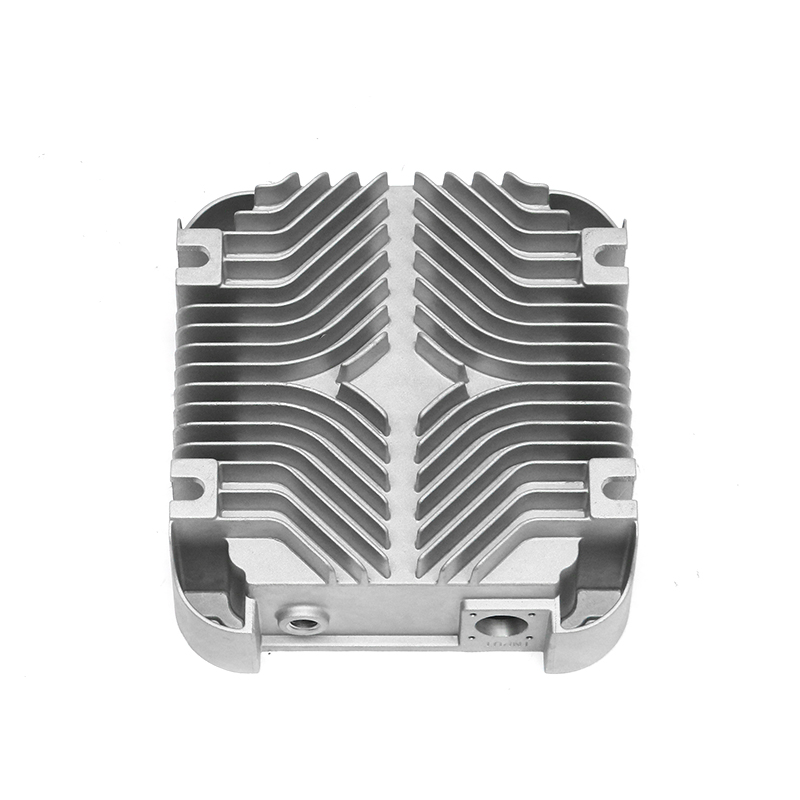
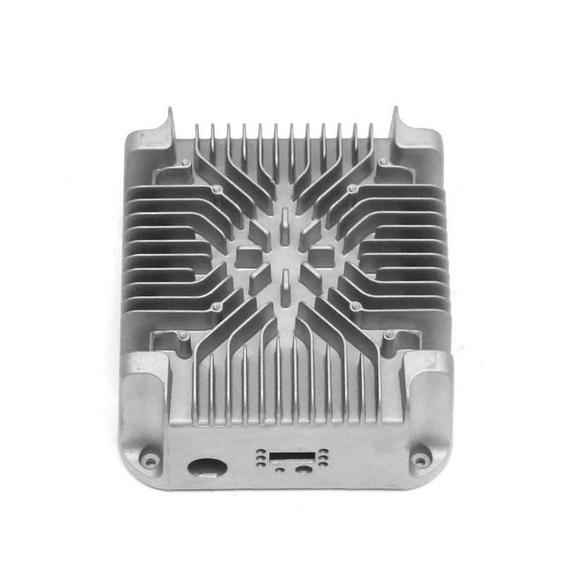
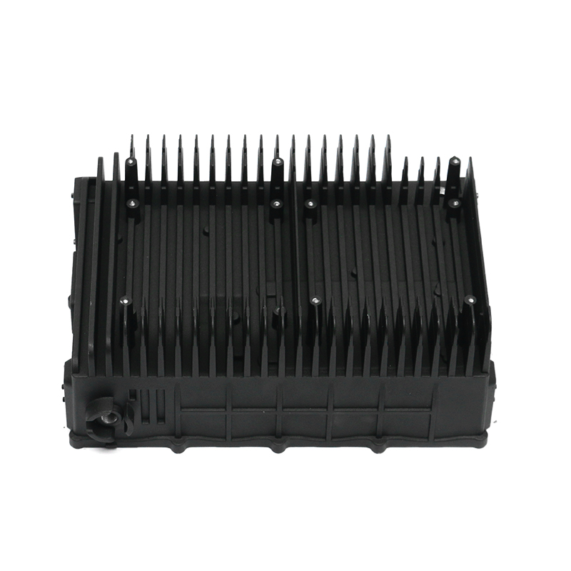
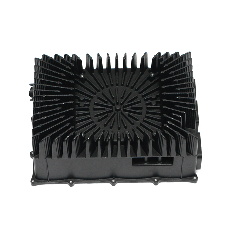
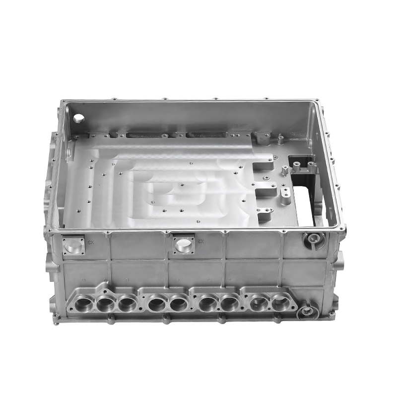
New energy electronically controlled air cooling die casting represents the definitive manufacturing methodology for producing high-efficiency thermal management housings used in electric vehicle (EV) motor controllers, on-board chargers, and power distribution units. By utilizing high-pressure die casting (HPDC) with advanced high-thermal-conductivity aluminum alloys, manufacturers can integrate complex micro-channel cooling fins directly into structural enclosures, reducing thermal resistance by up to 35% compared to multi-piece stamped assemblies. This lightweight, monolithic approach eliminates structural joints prone to mechanical separation under continuous vibrational stress, providing airtight sealing and rapid heat dissipation. As power densities in electric drivetrains exceed standard thresholds, these specialized die-cast components serve as a critical defense against thermal runaway in high-voltage silicon carbide (SiC) inverters.
Industrial data shows that standard aluminum castings possess thermal conductivities ranging between 90 and 120 W/m·K, which often proves insufficient for cooling high-density electronic modules. New energy air-cooled enclosures require precise control over solidification rates and alloy composition during the die casting process to eliminate internal porosity. Achieving this requires high-vacuum assistance during metal injection alongside automated mold temperature controllers. This specialized production framework ensures that thin-walled cooling fins, often down to 1.5 mm to 2.0 mm in thickness with a draft angle under 1 degree, are fully formed without cold shuts or air entrapment, creating an optimal pathways for forced-convection heat transfer.
Metallurgical Formulations and Thermal Conductivity Mechanics
The baseline performance of an air-cooled electronic enclosure depends heavily on the structural and thermal properties of the aluminum alloy utilized. Standard high-silicon casting alloys like AlSi9Cu3 offer excellent fluidity during manufacturing but compromise thermal performance due to the disruptive scattering of electrons within the dense silicon crystal lattice.
Low-Silicon, High-Thermal-Conductivity Alloys
To maximize heat dissipation, modern die casting facilities utilize specialized low-silicon, aluminum-magnesium-manganese or aluminum-iron-silicon formulations. These customized alloys achieve an enhanced thermal conductivity rating of 150 to 180 W/m·K in the as-cast condition. Minimizing the concentration of solution-hardened elements prevents local lattice distortion, allowing heat energy to transfer directly from the heating electronic substrate through the cast wall and out via the integrated air-cooling fins.
Microstructural Refinement During Solidification
Because low-silicon alloys have a higher shrinkage rate and a narrower processing window, the die casting machine must precisely control the injection parameters. The addition of trace grain refiners, such as titanium diboride (TiB2), ensures a uniform, fine-grained globular microstructure during fast cooling phases. This fine grain structure enhances the structural yield strength of the housing to exceed 140 MPa while preventing hot tearing along the base transitions of the cooling fins where stress accumulation is highest.
Manufacturing Process Mechanics and Precision Engineering
The production of complex electronically controlled cooling housings relies on multi-stage high-pressure die casting systems optimized for high integrity and repeatable dimensional tolerance. The process uses automated monitoring loops to manage velocity curves, pressure spikes, and vacuum extraction states.
High-Vacuum Assisted Cold Chamber Injection
Air entrapment during the high-velocity injection phase creates internal porosity that acts as an insulator, blocking heat paths through the enclosure wall. To prevent this, the mold cavity is connected to a high-capacity vacuum valve system that reduces internal cavity pressure to below 30 mbar before the molten alloy enters the gate. The real-time shot profile uses a multi-phase injection speed curve, where the slow shot phase transitions smoothly to a fast shot speed exceeding 5.5 m/s to fill the fine cooling fin gaps before solidification begins.
Intelligent Mold Temperature Regulation
Maintaining a precise thermal balance across the mold steel is critical when casting components with asymmetric geometries like air-cooling fins. Advanced die casting processes use automated oil or pressurized-water temperature control channels integrated directly inside the die blocks. The die surface temperature is held within a strict window of 180°C to 220°C. This thermal management prevents localized chilling zones that cause incomplete filling, while also avoiding overheating spots that can lead to soldering defects or surface blistering.
Comparative Analysis: Die Cast Cooling Formations vs. Machined Solutions
Selecting the correct manufacturing route for an electronic controller enclosure requires balancing mass-production throughput against structural and thermal capabilities. The table below outlines the comparative metrics of modern vacuum high-pressure die casting against multi-piece CNC-machined and welded assemblies.
| Evaluation Metric | Vacuum HPDC Air Cooling Housing | CNC-Machined Extruded Heat Sink | Friction Stir Welded (FSW) Assembly |
|---|---|---|---|
| Production Cycle Time | 45 - 75 seconds per part | 15 - 30 minutes per part | 8 - 12 minutes per part |
| Minimum Fin Thickness | 1.5 mm at apex | 1.0 mm uniform | 2.0 mm minimum |
| Interfacial Thermal Resistance | Zero (Monolithic integration) | High at mechanical joints | Low across weld line |
| Material Utilization Rate | > 95% (Gates and runners remelted) | 35% - 50% (High scrap generation) | 80% - 85% |
| Enclosure Protection Rating | IP67 / IP69K Compliant | Requires external gasket seals | Dependent on weld continuity |
Aero-Thermal Design Integration for Electronically Controlled Systems
The physical geometry of a die-cast air-cooled enclosure must be precisely balanced with the aerodynamic behavior of forced airflow systems. Advanced electronic control systems dynamically adjust cooling fan speeds based on real-time temperature feedback from internal power semiconductors.
Finned Array Optimization Mechanics
Designing the fin array requires balancing total surface area against pressure drop characteristics. An optimized fin pitch of 3.5 mm to 5.0 mm prevents boundary layer overlap, ensuring that air forced through the channel by electronic fans maintains a high convective heat transfer coefficient. If the fins are spaced too closely during the die design phase, the air flow stalls, increasing pressure drops and causing heat to trap near the core power modules.
Electronic Control Integration and Variable Flow Profiles
Modern electronic control systems use pulse-width modulated (PWM) fan controllers linked to internal temperature monitors. When temperature updates indicate transient power spikes within the inverter modules, the fan speed scales up immediately. The cast fin profile must be designed to promote turbulent airflow at these higher velocity ranges, breaking up insulating boundary layers and accelerating thermal energy transfer away from sensitive electronic surfaces.
Quality Control, NDT Testing, and Reliability Standards
Because electronically controlled housings shield high-voltage components, any mechanical failure or moisture leakage can result in catastrophic electrical shorting. Quality validation processes must enforce rigorous non-destructive testing (NDT) standards across high-volume production lots.
Industrial Real-Time X-ray Computed Tomography
Every batch of cast housings undergoes real-time inline X-ray inspection to detect internal porosity or shrinkage defects. Any structural void exceeding 0.3 mm in critical sealing regions or near fin roots triggers an automatic reject. This helps ensure that subsequent machining processes do not breach internal gas pockets that could compromise air tightness or structural integrity under thermal stress.
Helium Mass Spectrometer Leak Testing
To verify compliance with IP67 and IP69K moisture protection standards, finished castings are subjected to automated helium leak testing. The housing cavity is sealed, evacuated, and pressurized with a helium gas tracer mix. The maximum allowable leak rate is restricted to less than 1x10^-5 mbar·l/s, confirming that the monolithic die-cast part provides a reliable barrier against environmental dust, mud, and pressurized water sprays over the vehicle's operational lifecycle.
Operational Management and Maintenance of Die Casting Tooling
Maintaining precision dimensional stability across high-volume production cycles requires strict tool maintenance and surface treatment protocols. The thin, fragile mold sections needed to form air-cooling fins face severe thermal fatigue during operation.
- Premium Die Steel Selection: All mold inserts responsible for shaping high-density fin channels are fabricated using premium H13 hot-work tool steel or specialized maraging steels. This tool steel is subjected to multi-stage vacuum heat treatments to achieve a uniform tempered hardness of 46 to 50 HRC, which resists thermal checking.
- Advanced PVD Surface Coatings: To reduce molten aluminum soldering and erosive wear along the thin fin slots, mold cores receive advanced physical vapor deposition (PVD) coatings such as chromium nitride (CrN) or titanium aluminum nitride (TiAlN). These micro-coatings act as a thermal barrier, extending tool service life by up to 40%.
- Automated Micro-Spray Lubrication: Before each machine closure, an automated robotic manifold applies a precise film of water-free electrostatic die lubricant into the fin recesses. This micro-spray ensures clean part ejection without bending the hot, thin-walled aluminum cooling fins during the ejection phase.
- Stress Relief Tempering Cycles: After completing a fixed production interval—typically every 20,000 casting shots—the die steel is removed from the press and subjected to a thermal stress-relief tempering run. This preventive process removes accumulated residual stresses, preventing macro-cracking across the mold base.