

 English
 русский
 عربى
 Deutsch
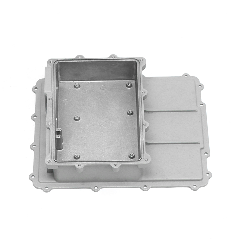
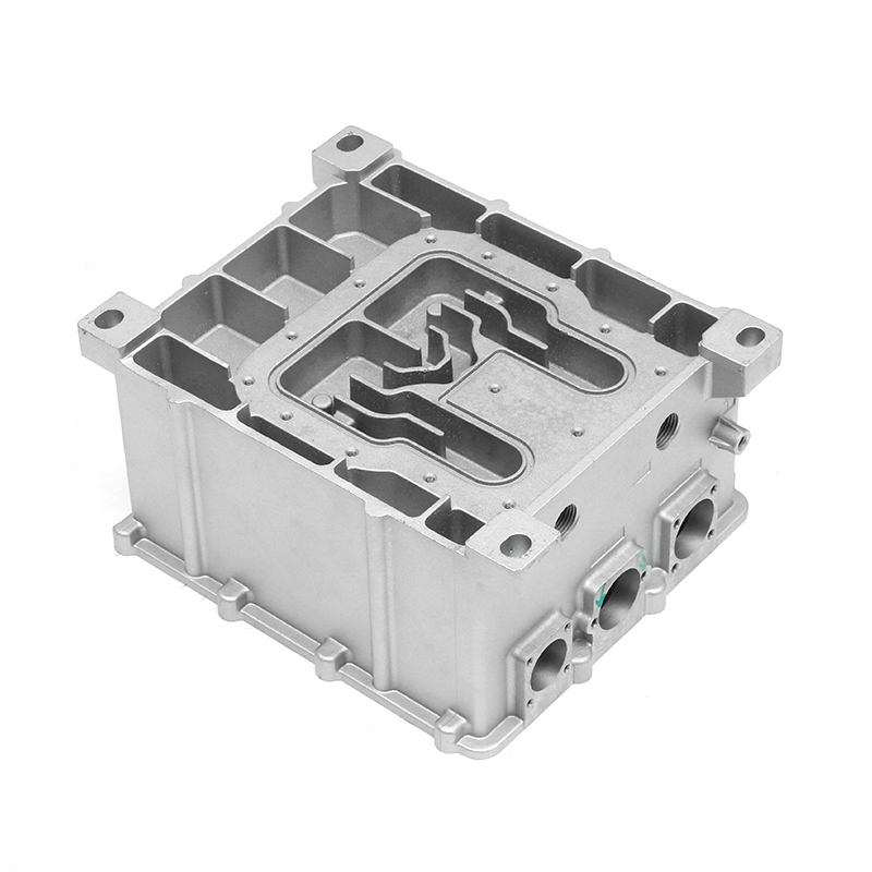
A 48 V electric control box can pass a bench IP67 check and still show a damp connector cavity after a winter road splash. The leak path is often not the gasket alone; it is the sealing flange flatness, the breather placement, or a porosity trail that opens during machining. That is why the vehicle electric control box housing should be treated as a sealing, thermal, and structural system, not as a metal box that holds a PCB.
The best housing design is usually the one with the fewest compromises: a stable die-cast sealing face, a cooling path that matches the power loss, and a validation plan that copies the vehicle environment. Thick walls rarely fix a thin design.
What the housing has to do before it looks like a part
An electric control box housing carries several jobs at once. It protects the electronics from dust, water, stone impact, and road salt. It supports connectors, busbars, PCB mounts, and sometimes a service access cover. It also provides a heat path from power devices to air or coolant, and it must survive vibration, thermal cycling, and mounting loads without losing sealing pressure.
- Keep water and dust out at the sealing flange, connector interfaces, breather, and service cover.
- Move heat from IGBTs, MOSFETs, or other power devices into fins, a cold plate, or an internal coolant channel.
- Carry structural loads from mounts, harnesses, and crash requirements without distorting the sealing face.
- Provide a stable ground path and, when required, EMI shielding at cover and connector joints.
Aluminum die casting is common for this part because it offers a good stiffness-to-weight ratio, good thermal conductivity, and the ability to form complex mounting bosses and cooling features in one casting. A wall thickness of roughly 2.5-4 mm is often used, but the right value depends on fill distance, load path, and porosity risk. Thin walls save mass; they also make filling and sealing-face stability harder.
Sealing starts at the flange, not the gasket
A gasket can only work with the surface it is given. If the sealing flange is twisted, too rough, or interrupted by a pore that reaches the machined face, the leak test will find it. A common starting point is a machined sealing face with flatness in the 0.05-0.10 mm range and surface roughness around Ra 1.6-3.2 um, but the final callout should follow the gasket supplier's compression data and the OEM specification.
Draft angle, ejector pin location, and gate placement also matter. A draft of 1-2 degrees is typical for die-cast walls, but the sealing flange may need a separate machining allowance so the gasket lands on a clean, flat surface. Porosity is the quieter risk: a small internal pore that intersects the sealing face after machining can become a leak path that only appears after thermal cycling. Pressure decay testing is common for production, while helium testing is used when the leak limit is very tight or the customer requires it.
Cooling path decides the housing shape
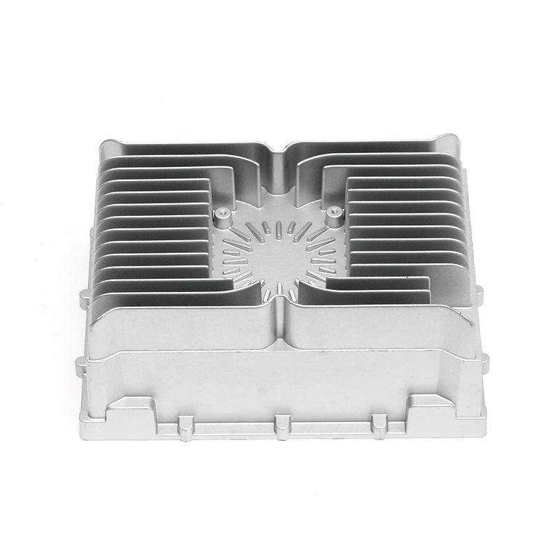
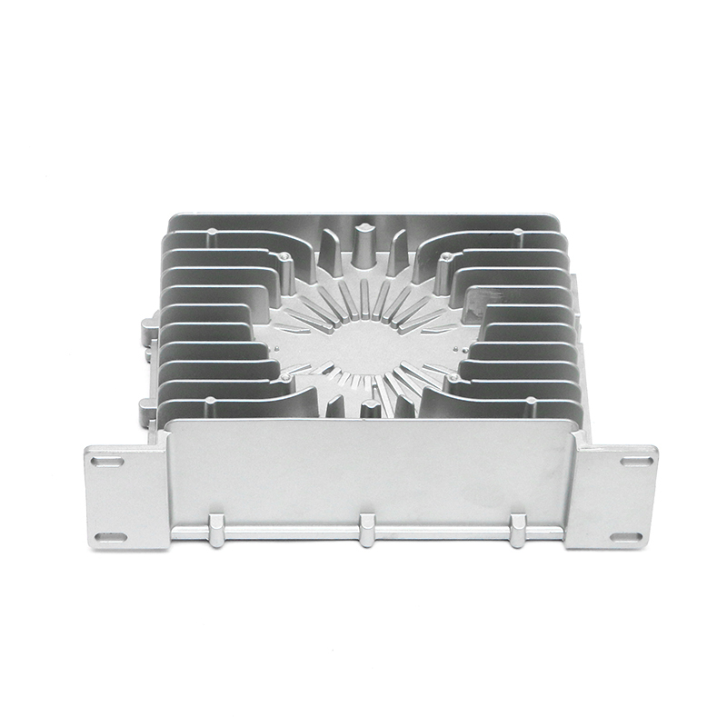
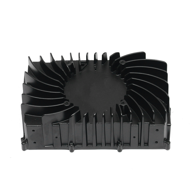
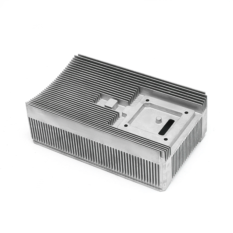
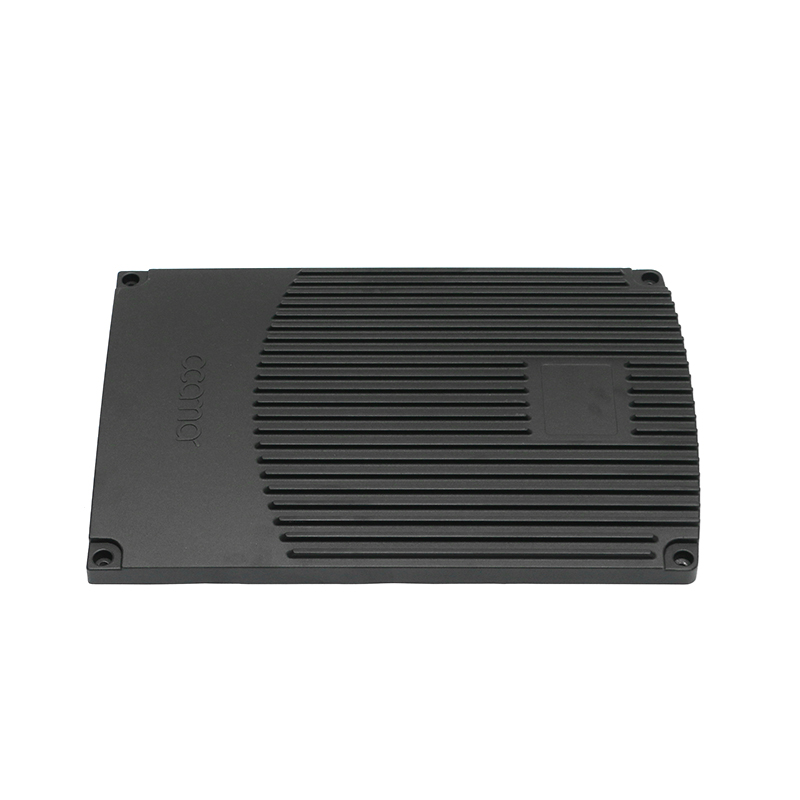
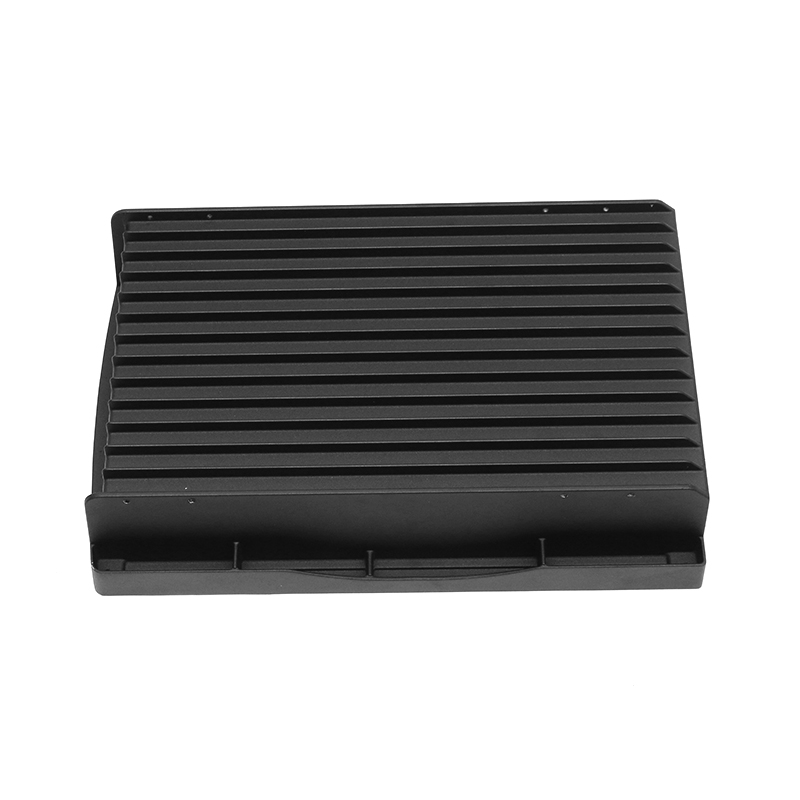
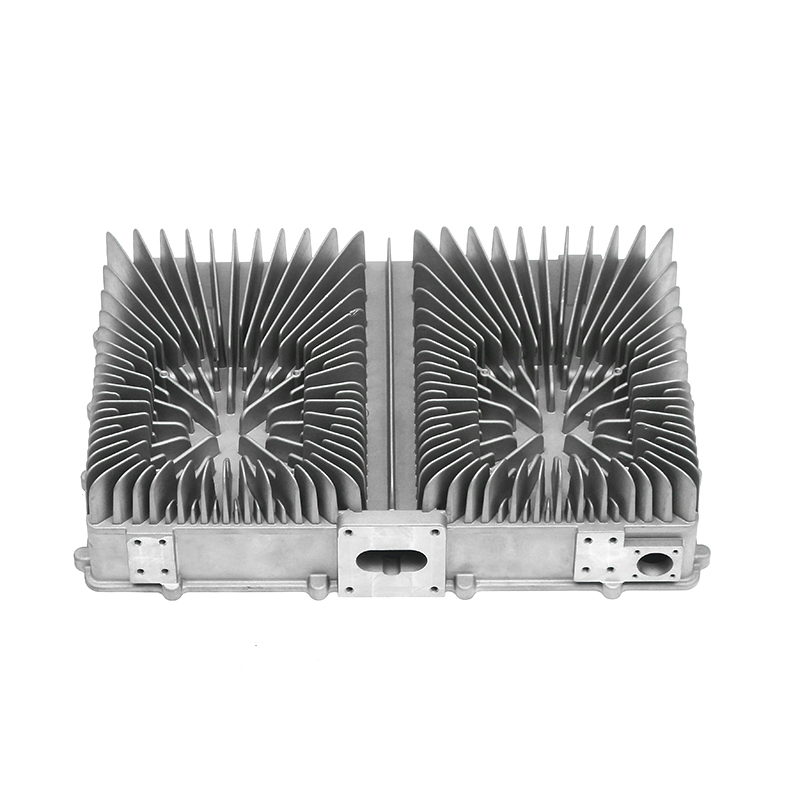
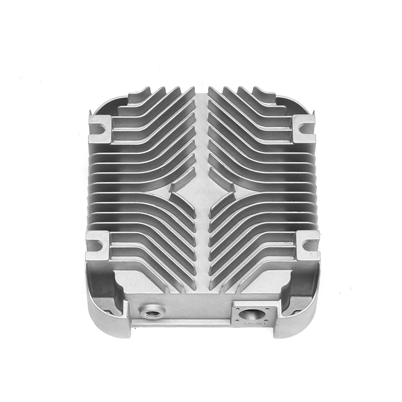
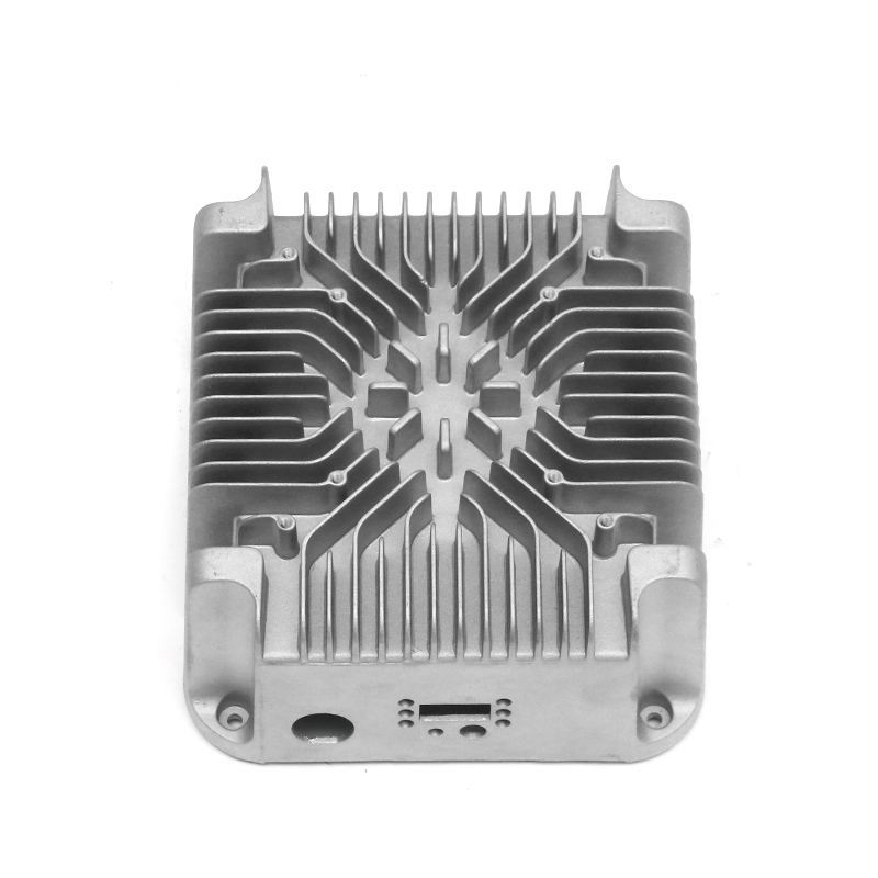
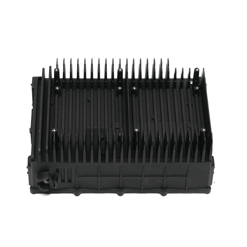
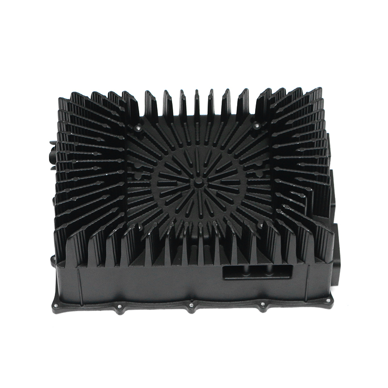
Air-cooled control box housings usually rely on external fins, open channels, and airflow from a fan or vehicle motion. They are simpler to cast, easier to service, and often cost less than liquid-cooled designs. The trade-off is heat rejection: air cooling works well for lower power loss, but it becomes bulky when the electronics demand a high continuous current.
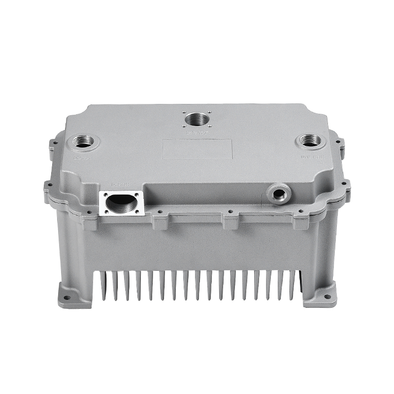 New Energy Electronically Controlled Air Cooling Die-Casting SeriesCustomized molds and lightweight aluminum die castings for air-cooled electronic control boxes and motor controllers, with IATF 16949-supported quality control.View Product →
Liquid-cooled housings use internal channels or a joined cold plate to move heat into a coolant loop. They can handle higher power density in a smaller package, but they add process risk: channel geometry, wall thickness around the coolant, and joint integrity all affect durability. Friction stir welding is often used for aluminum channel closure because it avoids the porosity and distortion risks of some fusion welding routes. The sealing strategy also changes, because coolant ports and channel walls become new leak boundaries. Designs for water-cooling housings in extreme environments usually combine pressure cycling, thermal shock, and corrosion testing rather than relying on a single leak check.
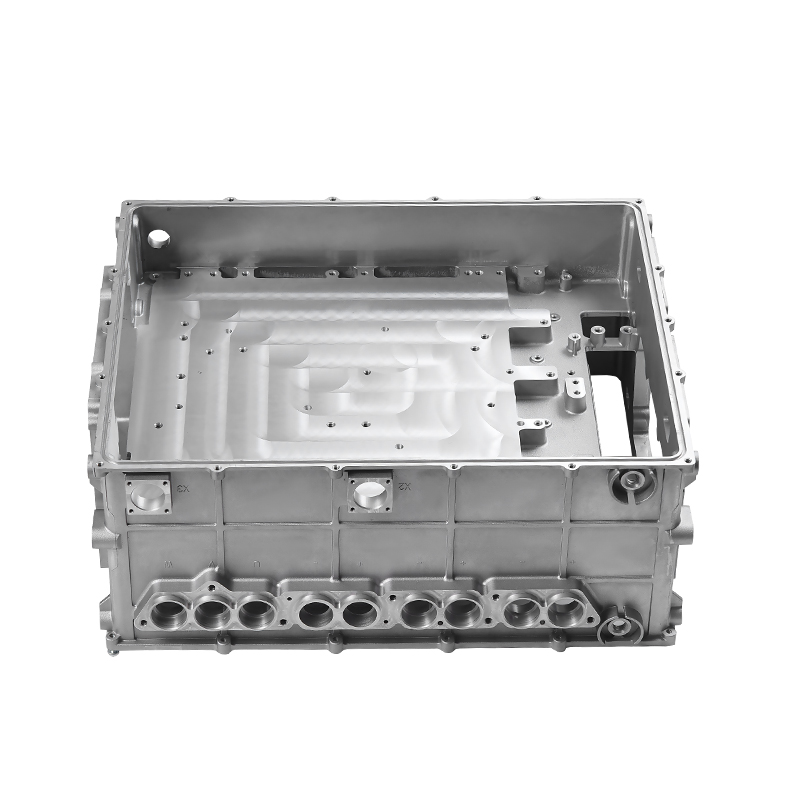 New Energy Electronically Controlled Water Cooling Die-Casting SeriesOEM/ODM die-cast molds and components for EV water pumps, tanks, and radiators, supporting intelligent cooling control and thermal management.View Product →
The practical choice is not air versus liquid in the abstract. It is whether the housing can remove the actual power loss at the worst ambient condition, without making the sealing face or the mounting structure less stable. A housing that is cool on the bench but leaks after 500 thermal cycles is not a cooling success.
Wall thickness, draft, and porosity are cost drivers
Most housing cost is fixed early, in the casting and machining concept. A design with thick walls may look strong, but it can create shrinkage porosity, longer cycle time, and heavier parts. A design with very thin walls may fill poorly and leave the sealing flange unstable after machining. The useful question is where mass is needed and where it is only adding risk.
| Design area | Air-cooled housing | Liquid-cooled housing | Production impact |
|---|---|---|---|
| Wall thickness | Often 2.5-3.5 mm | Often 3.0-4.5 mm around channels | Thin walls save mass but raise fill and porosity risk. |
| Sealing face | Machined cover flange | Cover flange plus coolant port faces | Flatness and surface finish drive leak rate. |
| Cooling feature | Fins or open channels | Internal channels, often friction stir welded | Channel inspection and leak testing are mandatory. |
| Validation focus | Airflow, dust, thermal soak | Coolant pressure, thermal shock, corrosion | The test sequence should match vehicle duty. |
Validation should mirror the vehicle, not the bench
A housing that passes a static leak test may still fail in service if the test ignores vibration, thermal expansion, and connector loads. Validation should reproduce the order in which the vehicle loads the part: assembly, transport, installation, thermal cycling, vibration, splash, and pressure change.
A practical validation sequence
- Material and casting approval: spectrum check, X-ray or industrial CT, and agreed porosity limits in critical sections.
- Machining approval: CMM inspection of mounting faces, sealing flange flatness, port position, and surface roughness.
- Leak test: pressure decay for production, helium for tight limits, and a defined re-test after thermal shock.
- Environmental test: thermal shock, vibration, IP6K9K splash, salt spray, and pressure cycling where coolant is present.
- Production control: PPAP, capability studies on critical dimensions, and change control for mold repairs or machining edits.
IATF 16949:2016 is a useful baseline because it forces the supplier to connect design records, process controls, and corrective action. It does not replace the housing-specific validation plan, but it makes the plan auditable.
What to ask a die-cast housing supplier
The supplier should be able to explain how the sealing face stays flat after machining, how porosity is controlled in the casting, and how the cooling path is inspected. A supplier that only quotes a price per kilogram is not answering the questions that matter for an electric control box housing.
- Can you cast and machine the sealing face with a controlled fixture and report flatness on the production drawing?
- How do you define and inspect porosity near sealing faces, coolant channels, and mounting bosses?
- What leak test method do you use, and how do you correlate it with the vehicle requirement?
- Do you have in-house mold maintenance, friction stir welding, CMM, and industrial CT capability, or are these outsourced?
- How do you handle engineering changes after PPAP, especially mold repairs that affect the sealing face?
At Fenda, the housing route covers mold design, 400T-2000T die casting, CNC machining, friction stir welding, CMM and industrial CT inspection, and leak testing under one roof. That vertical control is useful because the sealing face, the cooling channel, and the final leak result are not separate problems; they are one manufacturing chain.
The practical takeaway is simple: specify the vehicle electric control box housing around the sealing face, the thermal path, and the validation sequence, then choose a supplier who can show data for all three. A housing that is easy to cast but hard to seal will cost more in warranty than it saves in piece price.
Start with the worst-case thermal load and the most severe splash condition, then work back to wall thickness, flange design, and leak test limits. That order keeps the housing a reliable part of the electronics package, not a late-stage fix.